Welcome: Shenzhen Easton Technology Co., Ltd
Language:
 ∷
∷

∷
 ∷
∷
一、K-1000C system features:
1、32 to 65536 degree Gray control, Gamma correction procession handle.
2、Support various point, line light source, and all kinds of rules and specific shaped handle.
3. The controller has one output port, can support up to 512/2048 pixels(DMX lighting support up to 512 pixels).
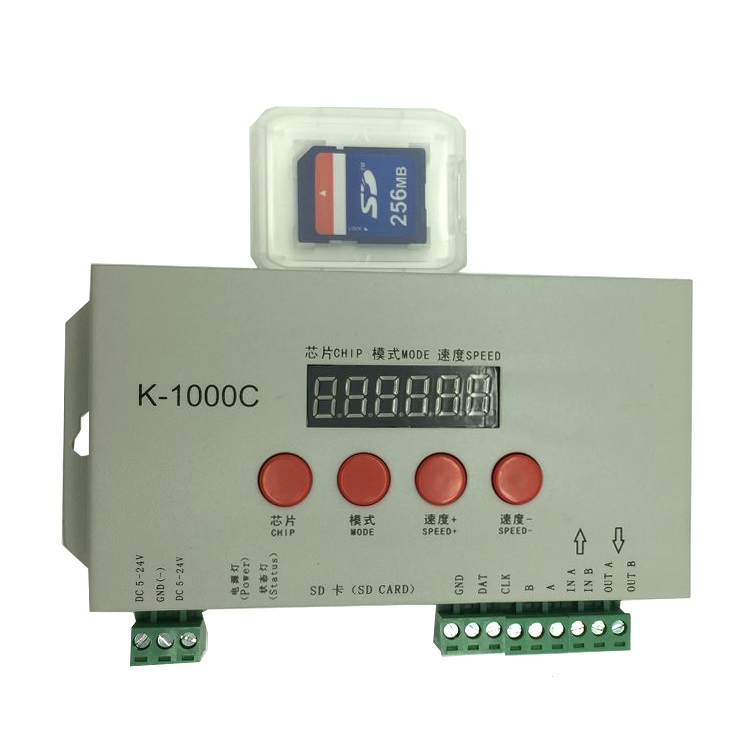
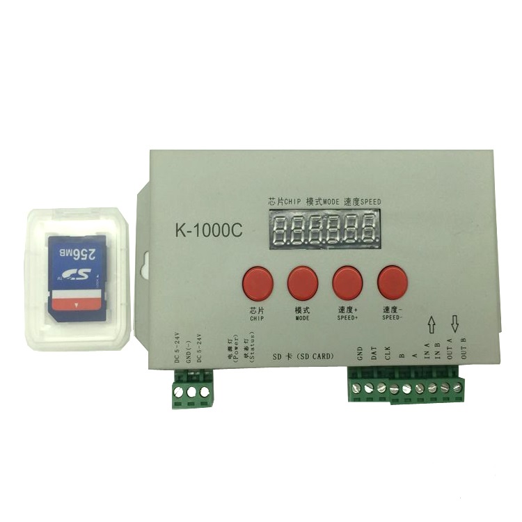
4、Play content stored in the SD card , the SD card can store up to 32 effects File, SD card capacity support 128MB-32GB.
5、The controller can single set use,also multiple controllers cascade, cascade optical isolation mode: interference, better stability, cascade distance between two controllers can reach up to 150 meters, need to use 0.5M² pure copper power cord.
6、The controller support chip can lock the support IC in software, or not lock the support IC in the software, select the support IC through the controller CHIP button, this scheme is more flexible and convenient.
7、For the DMX lighting IC, the controller comes with write address function; In addition, with use of our 2016 LedEdit-K V3.26 or later edition can make one key write address function setting.
8、Support load lamp is 4 channels (RGBW) pixels, or split into single channel point pixels.
9、Enhanced 485 TTL and 485 differential (DMX) signal output.
10、The controller comes with the test effects were as follows: 1 red, green, blue and black jump; 2 red, green, blue and black gradient; 3 red, green, blue and goes.
Notes: 1, The controller load lamps 512 points pixel, speed can reach up to 30 frames / sec, 1024 point pixel speed can reach up to 25 frames / sec, 2048 point pixel speed is about 15 frames / sec (the above parameter is an example of 1903 agreement IC, different IC have difference)
2. International standard DMX512 (1990 agreement) maximum support 512 pixels. When the load is international standard 170 pixels, the speed can reach up to 30 frames / sec, 340 pixels speed is about 20 frames / sec, when 512 pixels speed is about 12 frames / sec.
3. For the Beidou wireless synchronization function, please contact sales or technical support for details.
Support chips(PC Software Select K-1000-RGB):
00: UCS1903,1909,1912,2903,2904,2909,2912;TM1803,1804,1809,1812;
SM16703,16709,16712;WS2811,WS2812,WS2813,WS2815,WS2818;
INK1003;LX3203,1603,1103;GS8205,8206;SK6812(max. Supports lights 2048
pixels)
01:SM16716,16726(support up to 2048 pixels)
02:P9813(support up to 2048 pixels)
03:LPD6803(support up to 2048 pixels)
04:LX1003,1203(support up to 2048 pixels)
05:WS2801(support up to 2048 pixels)
06:LPD1886(support up to 2048 pixels)
07:TM1913(support up to 2048 pixels)
08:TM1914(support up to 2048 pixels)
09:P9883,P9823(support up to 2048 pixels)
10:DMX(support up to 512 pixels, suggest to support ≤320 pixels)
11:DMX 500K(support up to 512 pixels, suggest to support ≤320 pixels)
12:DMX 250K-CZF (support up to 512 pixels, suggest to support ≤320 pixels)
13:DMX 250K-CZF (support up to 512 pixels, suggest to support ≤320 pixels)
14: UCS5603-Test
15: UCS5603A(Max:2048Pixels)
16: UCS5603A(Max:2048Pixels)
17: TM1814
18: INK1003
19: APA102
NOTES: 1.If support RGBW four channels’ lights should select K-1000-RGBW.
2.If support single channel light should choose K-1000-W, at this time, one channel means one pixel, the software effect make as white lighting.
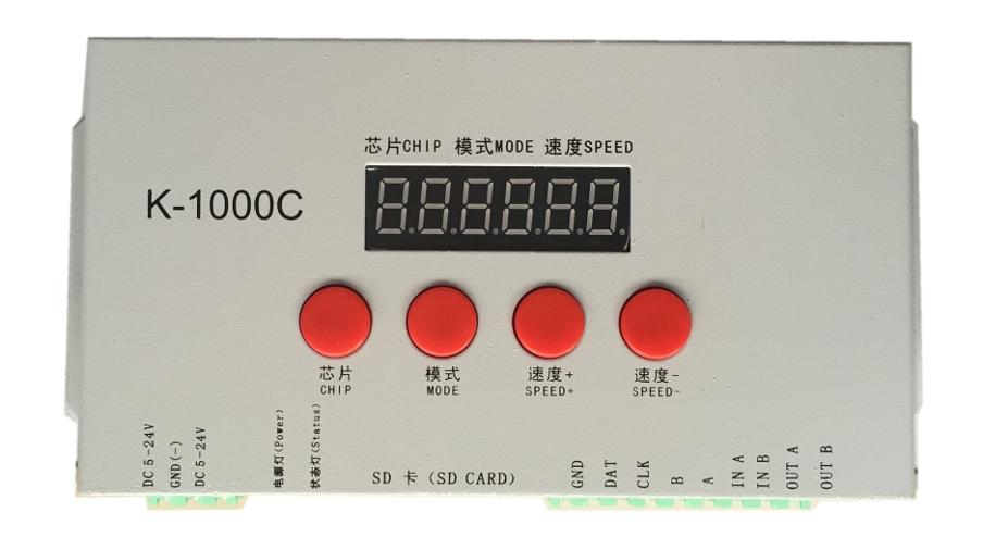
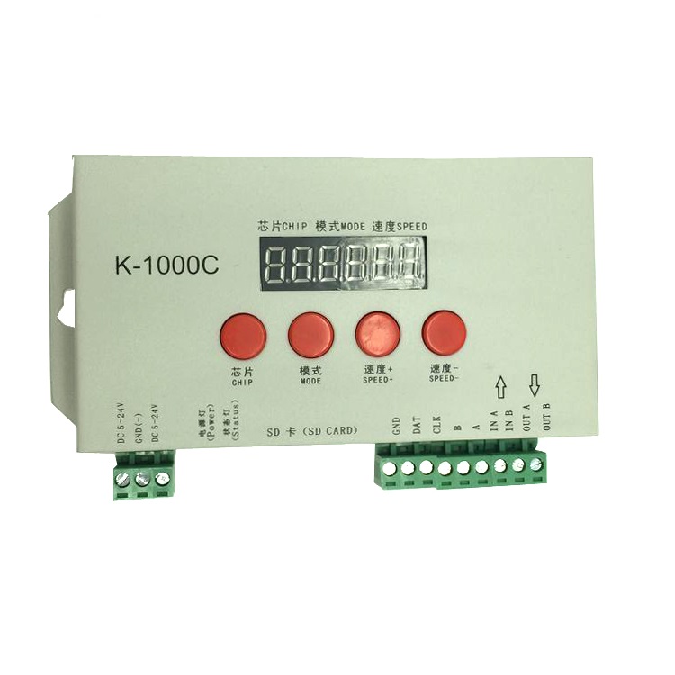
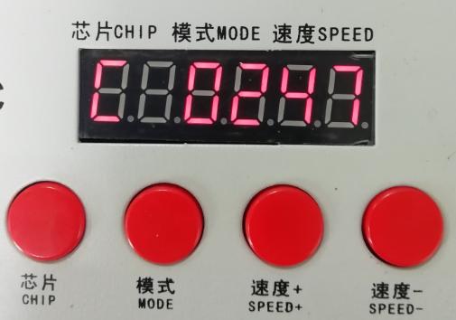
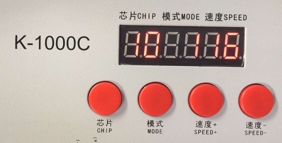
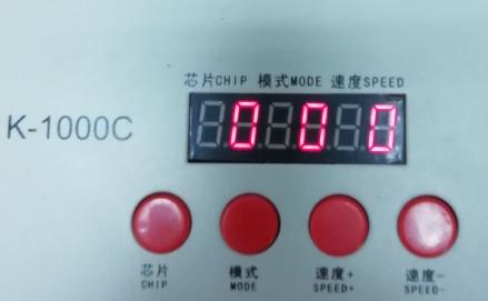
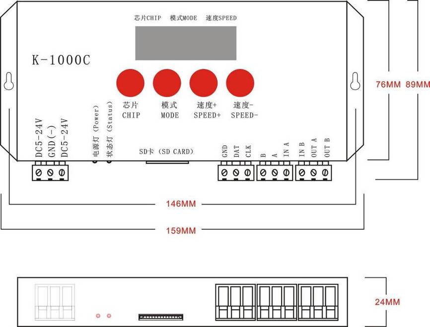
Screen print meaning:
Button meaning:
|
Button |
Meaning |
|
|
CHIP |
Switch chip |
Press CHIP and then MODE button, can enter write code mode, 61 means UCS512-A/B coding; 62 means WS2821 coding; 63 means SM512 coding, 64 means UCS512-C coding |
|
MODE |
Switch file |
|
|
SPEED+ |
Speed up |
Press SPEED+ and SPEED- the same time, would enter effect files looping mode. |
|
SPEED- |
Speed down |
|
Interface Meaning:
|
DC 5-24V |
5v-24V DC power positive input |
|
GND |
DC power supply negative input |
|
POWER |
Power indicator |
|
ERROR |
Status Indicator |
|
SD card(SD CARD) |
SD card slot |
|
GND |
Ground line |
|
CLK |
Clock line(Coding line if DMX lights) |
|
DAT |
Data line |
|
B |
Signal - |
|
A |
Signal + |
|
IN A |
Cascade sync signal, connect the front OUT A |
|
IN B |
Cascade sync signal, connect the front OUT B |
|
OUT A |
Cascade sync signal, connect the next IN A |
|
OUT B |
Cascade sync signal, connect the next IN B |
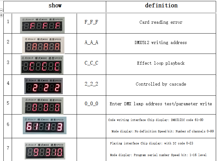
Display glossary (six-digit digital screen)
the corresponding frame rate of speed level:
|
Speed Level |
Frame Rate/Sec |
Speed Level |
Frame Rate/Sec |
|
1 |
4 frame |
9 |
14 frame |
|
2 |
5 frame |
10 |
16 frame |
|
3 |
6 frame |
11 |
18 frame |
|
4 |
7 frame |
12 |
20 frame |
|
5 |
8 frame |
13 |
23 frame |
|
6 |
9 frame |
14 |
25 frame |
|
7 |
10 frame |
15 |
27 frame |
|
8 |
12 frame |
16 |
30 frame |
Conventional IC lamps wiring
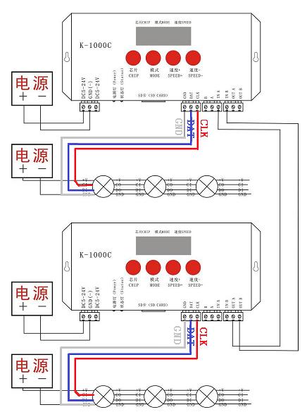
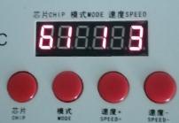
NOTE:1.When multiple controllers cascade, beginning from the second controller digital screen display 222, and status lights: on, off, on, off, strobe, all cascade controllers’ playback speed controlled by the first set.
Support write address code chip:
61:UCS512-A\B series
62:WS2821\2
63:SM512AP
64:UCS512-C series
65:SM16511\2-RGB series
66:SM16511\2-RGBW series
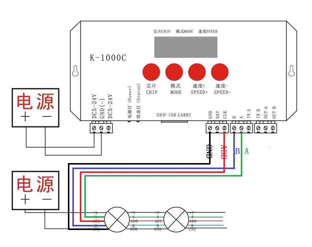
Controller support DMX lights coding and wiring method:
Two signal wiring diagram:
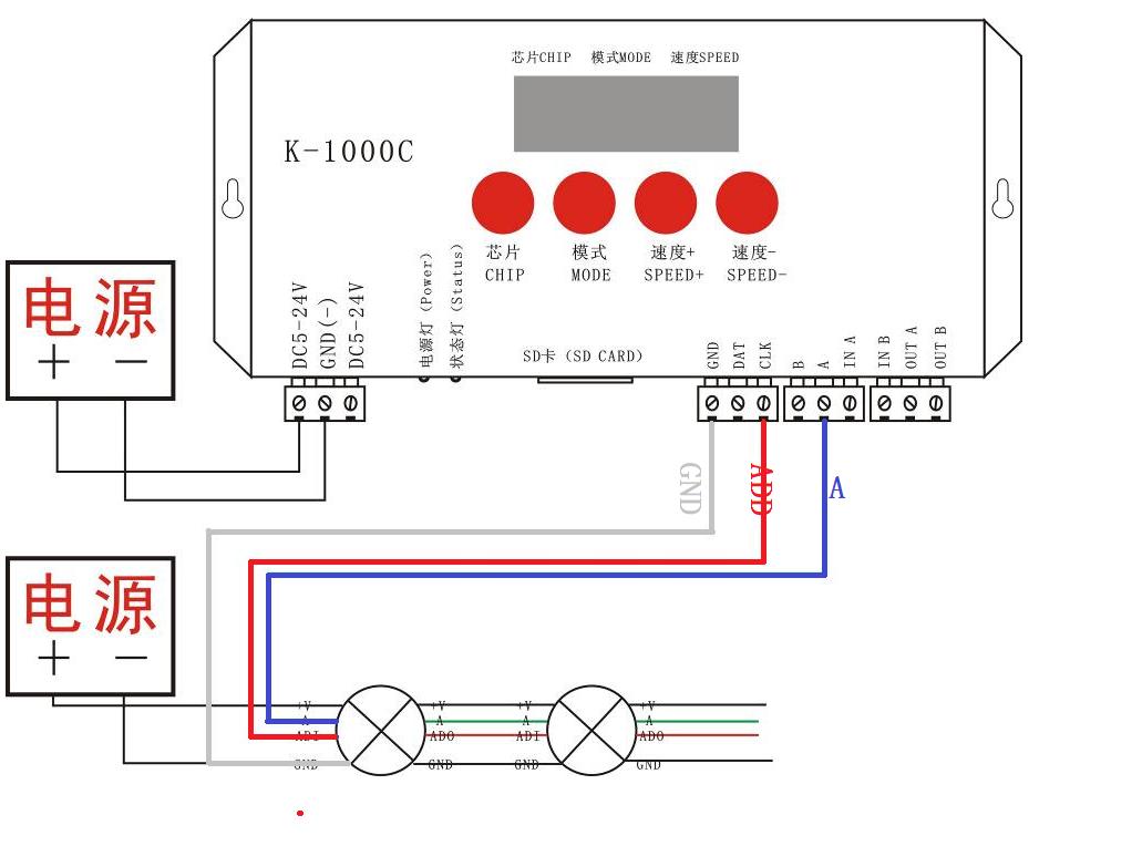
Single signal wiring diagram:
DMX512 lamp writing code and lamp address test
1. Connect the wires as shown above to start the controller. Press and hold the "Chip CHIP" first, and then press the "MODE" button to switch to the address writing mode, the following figure is displayed: "61_*_3",
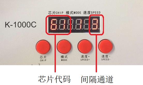
2. Press the "Chip CHIP" key to select the DMX512 loaded IC model; "Speed +" and "Speed -" to select the lamp interval channel (0-99).
The DMX512IC code is shown in the table below:
|
Appendix: DMX512IC code and IC correspondence table |
|||
|
61: UCS512A/B,TM512A/B |
62: WS2821 |
63: SM DMX512AP-N |
64: UCS512C*,TM512C* |
|
65: SM1651*-3CH |
66: SM1651*-4CH |
67: UCS512D* |
68: UCS512E* |
|
69: UCS512E(Self-channel number setting) |
70: SM17512 |
71: SM1752* |
72: UCS512F |
|
73: TM512C |
74: SM17500Normal address |
75: SM17500(Self-channel number setting) |
76: SM17500Self-channel address |
|
77: GS8512 |
78: GS8512 Write a single address |
79: GS8512 Set to no address mode |
80: QED512P |
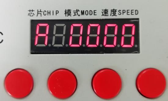
4. After writing the address code, the controller enters the DMX512 lamp channel test mode: the digital screen displays A 0000;
5. Press the "MODE" key to enter the automatic test mode, the display is "A ****" (* is the number of channels), the lamps will automatically start from the first pixel point and turn on white light in sequence;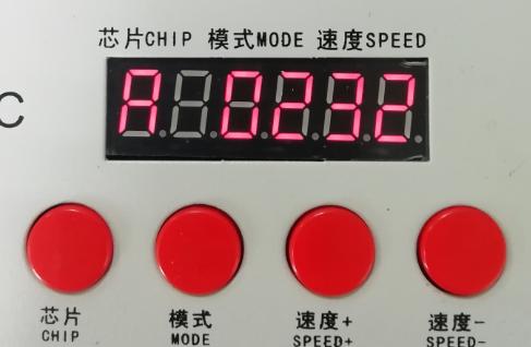
6. Press the "MODE" key again to enter the manual test mode, the display is "C ****" (* is the number of channels), "speed +" and "speed -" can adjust the pixel point (long press "speed +" Or "speed-" can increase or decrease rapidly), the pixel points of the lamps are lit one by one;
7. After the test is completed, press "Chip CHIP" to exit the channel test and return to the code writing interface;
8. First press the "chip CHIP", then press the "MODE" button to switch to the playback mode, and switch the chip to Chip: 10 at this time, it is the DMX512 standard protocol 250Kbps playback mode, and press the mode button and the speed button at this time You can switch the playback mode and adjust the speed respectively, as shown in the figure below:
One-key addressing of DMX512 lamps
1. When the software is writing the program output, click the button to enter the one-key address writing interface
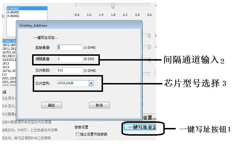 2. Interval channel input
The interval channel is input according to the actual value of the lamp, and the value is the number of channels occupied by a DMX512 IC to control the pixel of the lamp.
3. Chip model selection
Click the drop-down button to select the chip model corresponding to the DMX512 IC loaded by the lamp.
4. Complete the one-click address setting
Confirm that the settings are correct, click the confirm button to complete the program output
5. One-key programming operation of the controller
① Insert the SD card into the controller;
② Power on the controller and turn it on;
③ Long press the "MODE" button for 5 seconds, the controller displays "A-A-A", that is, the address is being written;
④ After the address is written, the controller will also enter the channel test mode (the same as the channel test after manual address writing).
⑤ After completing the channel test, press the "chip" key to exit the test mode, and the controller will return to the playback mode and work normally
DMX512 lamp test
1. Press the "Speed -" button to power on, enter the lamp test interface, and display 0 0 0
2. Enter the test lamp address interface for about 2 seconds without any operation, and the controller will display A3 0000
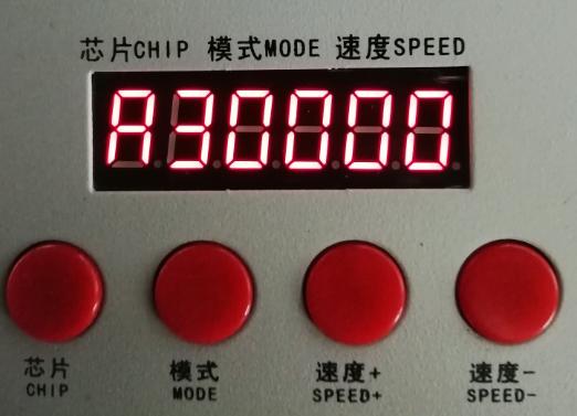
Press the "MODE" button to start the automatic test of the lamp address.
|
Appendix: Display glossary definition table |
|||
|
Automatic mode |
definition |
Manual mode |
definition |
|
A 1 **** |
1Channel automatic test |
C1 **** |
1Channel manual test |
|
A 2 **** |
2Channel automatic test |
C2 **** |
2Channel manual test |
|
A 3 **** |
3Channel automatic test |
C3 **** |
3Channel manual test |
|
A 4 **** |
4Channel automatic test |
C4 **** |
4Channel manual test |
SD card format
1. Before copying files to the SD card, the SD card must be formatted (note that it must be formatted before each copy).
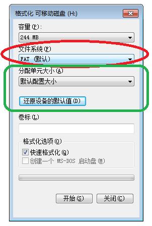
2. Formatting program
① SD card settings—"File system", "FAT" format (SD card capacity ≤ 2G) or "FAT32" format (SD card capacity ≧ 4G).
②SD card settings—"allocation unit size", click the drop-down button to select "default configuration size" or click the "restore device defaults" button.
③Start formatting.
As shown below:
3. The SD card cannot be hot-swapped, that is, every time the SD card is inserted or removed, the controller must be disconnected from the power supply.
Attached to common problems:
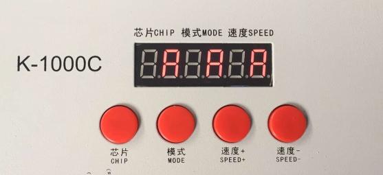
Question 1: After power on, it is found that the controller screen displays F F F, and there is no effect output
Answer: The FFF displayed on the screen means that the controller has not read the card correctly. The possible problems are:
①The SD card is empty and there is no effect file.
②The effect file *.led in the SD card does not match the controller model. Please select the controller model and chip model correctly in the latest version of 2016LedEdit, and recreate the effect file *.led.
③Test again after replacing the SD card to rule out the possibility that the SD card is broken.
Question 2: After power on, it is found that the controller outputs built-in effects, and there is no SD card effect playback
Answer: The controller cannot detect the SD card, and automatically plays the built-in program:
① The SD card is not inserted in the controller, and the SD card is inserted.
②The card has been inserted, but the SD card is not in place, reinsert the SD card
③The card has been inserted, the controller does not match the SD card, and the SD card cannot be detected, replace the matching SD card.
Question 3: After the controller is powered on, the indicator light is normal, but the lamp has no effect change
Answer: The reasons for this situation are as follows:
① Please check whether the signal line of the lamp and the controller are properly connected.
②The signals of conventional lamps are divided into incoming and outgoing signals. Determine whether the control is the signal incoming of the first lamp connected.
Question 4: After the controller is connected to the lamp, the lamp flashes and the effect changes, and the controller indicator shows normal.
Answer: ①The ground wire between the controller and the lamp is not connected.
②The effect made in the SD card is wrong, and the lamp chip selected when making the effect does not match the chip of the actual lamp.
③If the chip is not locked when making the effect on the software, press the chip of the controller to the corresponding chip of the lamp. For details, refer to the IC sequence on the sticker on the controller.
④The power supply voltage of the lamp is insufficient.
Question 5: The SD card cannot be formatted.
Answer: ①First, confirm whether the protection switch on the side of the SD card has been unlocked. The direction of unlocking is the gold pin end of the SD card.
②The protection lock has been designed according to the requirements, but it still cannot be formatted. If this happens, most of the SD card reader is broken, please replace the SD card reader (it is recommended to use a better quality card reader, and SSK( Biao Wang) card reader).
③If none of the above operations can solve the formatting problem, please replace the SD card and retest
Contact: luis lee
Phone: 13049850031
Tel: 13554982239
Email: sales@oureaston.com
Add: Shangpai Industrial Zone,Shiyan Town, Baoan District, Shenzhen
 Skpye
Skpye Whatsapp
 WeChat